BGP route-reflector-client

BGP requires that all internal BGP speakers are fully meshed. To reduce the size of the mesh, BGP speakers can be configure as route reflectors. Route reflectors pass internal learned routes to a set of internal BGP neighbors. When route reflectors clients are configured, the route-reflector is responsible for distributing internal BGP routes to other internal BGP neighbors.
Use the neighbor route-reflector-client command to identify the

Following is an example,
Here Hub router is configured as Multipoint and having two spokes R2 & R4. Where R2 is connecting with R6 and establishing EBGP peer relationship. In order to advertise routes originated by R2 to other peer as R3, the Hub router is reflecter and R2 is configured as Route-reflector-client.
HUB#show run s bgp
router bgp 200
no synchronization
bgp cluster-id 11.11.11.11
bgp log-neighbor-changes
neighbor 172.16.13.3 remote-as 200
neighbor 172.16.13.3 route-reflector-client
neighbor 172.16.124.2 remote-as 200
neighbor 172.16.124.2 route-reflector-client
neighbor 172.16.124.4 remote-as 200
no auto-summary

BGP ttl-security

The BGP Support for TTL Security Check feature is a lightweight security mechanism to protect (eBGP) peering sessions from CPU utilization-based attacks using forged IP packets. Enabling this feature prevents attempts to hijack the eBGP peering session by a host on a network segment that is not part of either BGP network or by a host on a network segment that is not between the eBGP peers.

This feature is enabled by configuring a minimum Time To Live (TTL) value for incoming IP packets received from a specific eBGP peer. When this feature is enabled, BGP will establish and maintain the session only if the TTL value in the IP packet header is equal to or greater than the TTL value configured for the peering session. If the value is less than the configured value, the packet is silently discarded and no Internet Control Message Protocol (ICMP) message is generated.

Configuration Example:

On R1:

R1(config)#router bgp 100
R1(config-router)#neighbor 172.16.0.1 ttl-security hops 5

Now R1 wills silently drop the packet because TTL value in the incoming packet should be 250 or greater.

On the other side neighbor we can configure ebgp-multihop to 250 or to ebgp-multihop which will set the default value to 255.

If we have frame-relay hub and spoke network then we have to configure the TTL value including additional hops also as traffic will go through hub router.

MPLS Label - Header

The MPLS labels are advertised between routers so that they can build a label-to-label mapping.
These labels are attached to the IP packets, enabling the routers to forward the traffic by looking at the label and not the destination IP address. The packets are forwarded by label switching instead of by IP switching.

The MPLS label also called a shim header is 32bit (4 octets). Below is MPLS label looks like..

A MPLS label contains the following parts.

20-bit label value
3-bit experimental field
1-bit bottom-of-stack indicator
8-bit time-to-live filed

First 20 bit defines the original length of the actual label. Next 3-bit is experimental field which is used to copy QoS value from IP header like IP precedence or DSCP values. After that we have Bottom-of-stack value which defines weather the label is a last label. If it is set to 0 then its mean there are more labels and set as 1 defines that it’s a last label in a packet. Last field contains the 8-bit Time-to-live field which is same as IP Header time-to-live value and copied from IP header at PE router. We can also disable copying of TTL value from IP header to MPLS label.

KnowledgeNet MPLS Lab in GNS3

Dear Readers,

I am posting GNS3 Topology and lab config for Basic MPLS lab presented in Knowledge Net Student Guide 2.0. I am sure this will provide useful help to the poeples who are in the journery of learning MPLS and save lot of time in configuring basic IP configuration and to setup basic lab. This is full configured and fuctional lab by using IOS "c3640-jk9o3s-mz.124-16.bin"

Click the below "Show Config" link to see sample config of PE11 Router and get complete configuration with GNS3 topology file from " knowledgnet mpls lab.zip

Show Config /Hide Config


CCIE R&S Certification v4.0

Effective from today:- October 19, 2009 Cisco CCIE® Routing and Switching v4.0 certification exams are now available in all VUE testing locations worldwide. I think lot of others like me were thinking about the 19 October who wish to get their CCIE # in R&S. Yes and from today our journey is specifically going to start on CCIE R&S version 4.

The competencies required for CCIE R&S v4.0 certification can be found on the Cisco Learning Network under CCIE R&S v4.0 written exam topics and CCIE R&S v4.0 lab exam topics in the CCIE R&S section of the site.

Both the written and lab exams have been refreshed with new questions covering MPLS and VPN networking. The written exam includes new scenario-based questions. The lab exam now requires hands-on troubleshooting of preconfigured networks, in addition to configuration. Exam duration and pricing will remain the same, with the two-hour written exam at USD $350.00 and the eight-hour lab at USD $1400.00

For more information regarding CCIE R&S certification 4.0 and related exams access the Cisco Learning Network at www.ciscolearningnetwork.com.

Good Luck!

GNS3 High Processor Usage

Guyes,
I was experienced an issue while doing labs in GNS3 that processor usage is going high after a certain time. Althogh it was not high in always and only at some occasion I have experienced problem.
The first thing comes in out mind to apply the best idlepc value which I already did. The idlepc values was ok with me and I am using from quite of time. I was using the following topology to run on my Dell Inspiron 640 notebook (2.0 GHz Core2Due with 2GB Ram).
The problem I found that while working on one router’s terminal session the others routers was going to logout me from their sessions and processor usage was going to high.
To resolve this I applied the following commands on the all routers.

Router(config)#line console 0
Router(config-line)#session-timeout ?
<0-35791> Session timeout interval in minutes
Router(config-line)#session-timeout 0 0
Router(config-line)#


The above allowed me to set the session to not time-out which was set for 10 minutes by default and Lab not giving the above problem any more.

Advantages of MPLS

· MPLS enables a single converged network to support both new and legacy services, creating an efficient migration path to an IP-based infrastructure. MPLS operates over both legacy (DS3, SONET) and new infrastructure (10/100/1000/10G Ethernet) and networks (IP, ATM, Frame Relay, Ethernet, and TDM).

· MPLS enables traffic engineering. Explicit traffic routing and engineering help squeeze more data into available bandwidth.

· MPLS supports the delivery of services with Quality of Service (QoS) guarantees. Packets can be marked for high quality, enabling providers to maintain a specified low end-to-end latency for voice and video.

· MPLS reduces router processing requirements, since routers simply forward packets based on fixed labels.

· MPLS provides the appropriate level of security to make IP as secure as Frame Relay in the WAN, while reducing the need for encryption on public IP networks.

· MPLS VPNs scale better than customer-based VPNs since they are provider-network-based, reducing the configuration and management requirements for the customer.

MPLS - Multi Protocol Label Switching

MPLS technology is around us since few years but the technology is awsome. The MPLS labels are advertised between routers so that they can build a label-to-label mapping. These labels are attached to the IP packets, enabling the routers to forward the traffic by looking at the label and not the destination IP address. The packets are forwarded by label switching instead of by IP switching.

The label switching technique is not new. Frame Relay and ATM use it to move frames or cells throughout a network. In Frame Relay, the frame can be any length, whereas in ATM, a fixed length cell consists of a header of 5 bytes and a payload of 48 bytes. The header of the ATM cell and the Frame Relay frame refer to the virtual circuit that the cell or frame resides on. The similarity between Frame Relay and ATM is that at each hop throughout the network, the "label" value in the header is changed. This is different from the forwarding of IP packets. When a router forwards an IP packet, it does not change a value that pertains to the destination of the packet; that is, it does not change the destination IP address of the packet. The fact that the
MPLS labels are used to forward the packets and no longer the destination IP address have led to the popularity of MPLS.

Logging and and using syslog

Cisco devices communicate with an administrator through system messages. These system messages are typically sent to a logging process, so they are most often called syslog messages. Syslog is also the name of the UNIX-based service that handles system messages from UNIX systems (and also Cisco devices if configured to do so).

Logging is enabled by default. The no logging on command actually forces system messages to the console. In fact, this can impede the performance of the Cisco device because processes must wait for messages to be written to the console before the processes can continue their operations. It is recommended that the administrator leave the logging process enabled (the default behavior); that way logging messages can be written to the console more efficiently.

Because there is really no way out to stop the sending of system messages to the console, administrators should use the logging synchronous command in line configuration mode. This command prevents these messages from "interrupting" typing at the console.

To have the Cisco device store syslog messages in an internal buffer, administrators should ensure the logging process is in its default enabled state (logging console command) and then use the command logging buffered. This will use a default size of 4096 bytes. This can be changed by specifying an optional size at the end of the logging buffered command. To view the contents of the buffer, there is the show logging command. The oldest messages display first. When the buffer fills to capacity, new messages overwrite the oldest messages. The buffer can be cleared anytime with the clear logging command.

Syslog messages can be stored on a server (UNIX- or Windows-based) in the network.
CiscoWorks LAN Management Suite (LMS) features a built-in syslog server application that stores these messages in a searchable database. It allows the filtering of messages, reporting on messages, and even action filters that allow automated responses to certain messages, including pages and e-mails.

To send system messages to a UNIX or CiscoWorks syslog server, ensure the logging process is enabled and then issue the command logging x.x.x.x, where x.x.x.x is the IP address of the syslog server. The command can be entered multiple times to configure multiple destinations for the messages. To limit the sending of all messages, use the logging trap level command, where level is the number or the name of the severity level. For example, logging trap notifications restricts the messages sent to only those of level 0 through 5. This keeps debugging and informational messages from being sent to the server. UDP port 514 is used for syslog messages, so be sure that your firewalls permit this port if you need the messages to pass through such devices.

UNIX syslog servers use a facility code to identify the source of syslog messages. They use this code to create different logs for the different sources of messages. Sample facilities include lpr for the Line Printer System and mail for the e-mail system. UNIX syslog servers reserve the facility codes local0 through local7 for log messages received from remote servers and network devices. To have switches use one log file on the server and routers use another, change the facility code for switches using the logging facility local6 command. By default, Cisco devices use local7 for their messages so that your router messages will be in a different log. Note that CiscoWorks requires the use of local7.

Some devices even allow logging of system messages to a file in flash memory. The command to do this is simply logging file flash:myname.txt. This command can also set size limits on the file and control the types of messages that are sent to flash.

Administrators should stamp syslog messages with the date and time that they were generated. This is accomplished with the service timestamps log datetime command.

Domain Name System

Cisco routers can participate in the Domain Name System (DNS). For example, you can specify a default domain name that the Cisco IOS Software uses to complete domain name requests. You can specify either a single domain name or a list of domain names. Any IP hostname that does not contain a domain name has the domain name you specify appended to it before being added to the host table. To specify this domain name, use the following command:
Router(config)# ip domain name name

To define a list of default domain names to complete unqualified host names, we use the following command:

Router(config)# ip domain list name

We can also specify DNS name servers for the router or switch to call on for name resolution. To do so, use the following command:

Router(config)# ip name-server server-address1 [serveraddress2 server-address6]

If you do not want to enable your router to use DNS for name resolution, you can use the following command to disable this default behavior:

Router(config)# no ip domain-lookup

Web Cache Communication Protocol

Web Cache Communication Protocol (WCCP) allows an administrator to forward web traffic to a Cisco cache engine. The Cisco cache engine reduces transmission costs and downloading time for clients. When users request web pages, the WCCP-capable router sends the requests to a cache engine. If the cache engine has a copy of the requested page in storage, the cache engine sends the user that page. If there is no cached copy, the cache engine retrieves the requested page from the web server, stores a copy, and forwards the page to the user. The routers and the cache engine operate transparently from the perspective of end users. End users do not know that the page came from the cache engine rather than the web server.

The global configuration command used on the router to enable the protocol is this:

ip wccp {web-cache service-number}
[group-address groupaddress] [redirect-list access-list]
[group-list access-list] [password [0-7] password]

To actually redirect traffic on an interface to a cache engine, use the following interface configuration command:

ip wccp {web-cache service-number} redirect out

DHCP with Cisco Devices

Cisco devices can function as DHCP servers. They can be configured to forward requests to secondary servers should the Cisco device be unable to satisfy the request. Figure 3-3 shows the four-step process that the router participates in to provide DHCP services.


Configuring a Cisco device as a DHCP server

To configure the DHCP address pool name and enter DHCP pool configuration mode, use the following command:

Router(config)# ip dhcp pool name

The DHCP server assumes that all IP addresses in a DHCP address pool subnet are available for assigning to DHCP clients. You must specify the IP address that the DHCP server should not assign to clients. To do so, use the following command:

Router(config)# ip dhcp excluded-address low-address [highaddress]

To configure a subnet and mask for the DHCP address pool, use the following command in DHCP pool configuration mode:

Router(config-dhcp)# network network-number [mask /prefixlength]

Additional DHCP pool configuration mode commands enable you to configure additional parameters for the scope, including default gateway, domain name, DNS server addresses, Windows Internet Naming Service (WINS) server addresses, and so on.

Network Time Protocol

There are many reasons that an administrator will want to keep the time accurate on all systems in the infrastructure. Network Time Protocol (NTP) assists the administrator in this goal by automatically synchronizing the time between network devices.

Devices in the network running NTP can receive the correct time from an authoritative time source, such as a Cisco router, a radio clock, or an atomic clock attached to a timeserver.

To configure a router to receive the time from an authoritative time source on the network, use the following command:

ntp server {{[vrf vrf-name] ip-address hostname} [version
number] [key key-id] [source interface] [prefer]}

Some platforms have a battery-powered hardware clock, referred to as the calendar, in addition to the software-based system clock. The hardware clock runs continuously, even if the router is powered off or rebooted. It is a good practice to periodically update the hardware clock with the time learned from NTP. To do this, use this command:

ntp update-calendar

To have the router provide the correct time for the network, we can use this command:

ntp master [stratum]

The stratum value is an indicator of how close a device is to the master time source. Consider it like a hop count. If you set the stratum to 1 on the router, you are indicating that it is itself the authoritative time source.

We can also have the router synchronize the clock of a peer router, or be synchronized from that peer. The command to configure this is as follows:

ntp peer {{[vrf vrf-name] ip-address hostname}[normalsync][
version number] [key key-id] [source interface] [prefer]}

Network Address Translation

Network Address Translation (NAT) allows an organization to use private IP address space inside the organization (or any other IP address it might require) and present this IP address differently to the outside networks. Organizations might use NAT for the following purposes:

■ To connect private IP internetworks that use nonregistered IP addresses to the Internet, NAT translates the internal local addresses to globally unique IP addresses before sending packets to the outside network.
■ Internal addresses must be changed, and this creates a large administrative burden. NAT is used instead to translate addresses.
■ To do basic load sharing of TCP traffic. A single global IP address is mapped to many local IP addresses by using the TCP load distribution feature.

NAT uses the following definitions:

■ Inside local address—The IP address that is assigned to a host on the inside network. Often, this is a nonregistered IP address.
■ Inside global address—A legitimate IP address that represents one or more inside local IP addresses to the outside world.
■ Outside local address—The IP address of an outside host as it appears to the inside network.
■ Outside global address—The IP address assigned to a host on the outside network by the owner of the host.

Ethernet

Ethernet refers to the family of LAN products covered by the IEEE 802.3 standard. This standard defines the carrier sense multiple access collision detect (CSMA/CD) protocol. Four data rates are currently defined for operation over optical fiber and twisted-pair cables:

■ 10 Mbps—10BASE-T Ethernet
■ 100 Mbps—Fast Ethernet
■ 1000 Mbps—Gigabit Ethernet
■ 10,000 Mbps—10 Gigabit Ethernet

Ethernet has replaced just about every other LAN technology because of the following reasons:

■ It is easy to understand, implement, manage, and maintain.
■ It has a relatively low cost.
■ It provides extensive topological flexibility.
■ It is a standards-compliant technology.

802.3

802.3 defines the original shared media LAN technology. This early Ethernet specification runs at 10 Mbps. Ethernet can run over various media such as twisted pair and coaxial. We often see 802.3 Ethernet referred to as different terms because of the differences in the underlying media.

Here are examples:

■ 10BASE-T—Ethernet over Twisted Pair Media
■ 10BASE-F—Ethernet over Fiber Media
■ 10BASE2—Ethernet over Thin Coaxial Media
■ 10BASE5—Ethernet over Thick Coaxial Media

802.3U (Fast Ethernet)

Fast Ethernet refers to any one of a number of 100-Mbps Ethernet specifications. As its name implies, Fast Ethernet offers speeds 10 times that of the 10BASE-T Ethernet specification. Although Fast Ethernet is a much faster technology, it still preserves such qualities as frame format, MAC mechanisms, and maximum transmission unit (MTU). These similarities permit you to use existing 10BASE-T applications and network management tools on Fast Ethernet networks.

802.3Z (Gigabit Ethernet)

Once again, this Ethernet technology builds on the foundations of the old, but it increases speeds tenfold over Fast Ethernet to 1000 Mbps, or 1 gigabit per second (Gbps).
802.3AB (Gigabit Ethernet over Copper)

Gigabit Ethernet over Copper (also known as 1000BASE-T) is yet another extension of the existing Fast Ethernet standard. 802.3AB specifiesGigabit Ethernet operation over the Category 5e/6 cabling systems already installed. This reuse of the existing infrastructure helps make 802.3AB a highly cost-effective solution.

10 Gigabit Ethernet

The latest in Ethernet technologies, 10 Gigabit Ethernet, provides the following features:

■ High bandwidth
■ Low cost of ownership
■ Scalability from 10 Mbps to 10,000 Mbps
Long Reach Ethernet
The Cisco Long Reach Ethernet (LRE) networking solution delivers 5 to 15-Mbps speeds over existing Category 1/2/3 wiring. As the name conveys, this Ethernet-like performance extends 3500 to 5000 feet.

EtherChannel

EtherChannel allows you to bundle redundant links and treat them as a single link, thus achieving substantial bandwidth and redundancy benefits. It is often advisable to use an EtherChannel for key trunks in your campus design. Notice that EtherChannel affects STP, because ordinarily one or more of the links would be disabled to prevent a loop.

Following are guidelines for EtherChannel:

■ All Ethernet interfaces on all modules must support EtherChannel.

■ You have a maximum of eight interfaces per EtherChannel.

■ The ports do not need to be contiguous or on the same module.

■ All ports in the EtherChannel must be set for the same speed and duplex.

■ Enable all interfaces in the EtherChannel.

■ An EtherChannel will not form if one of the ports is a Switched Port Analyzer (SPAN) destination.

■ For Layer 3 EtherChannels, assign a Layer 3 address to the portchannel logical interface, not the physical interfaces.

■ Assign all EtherChannel ports to the same VLAN or ensure they are all set to the same trunk encapsulation and trunk mode.

■ The same allowed range of VLANs must be configured on all ports in an EtherChannel.

■ Interfaces with different STP port path costs can form anEtherChannel.

■ After an EtherChannel has been configured, a configuration made to the physical interfaces affects the physical interfaces only.

EtherChannel load balancing can use MAC addresses, IP addresses, or Layer 4 port numbers—either source, destination, or both source and destination addresses.

Here is an example:

Router# configure terminal
Router(config)# interface range fastethernet 2/2 -8
Router(config-if)# channel-group 2 mode desirable
Router(config-if)# end

VTP pruning

VTP pruning enables you to limit the amount of traffic sent on trunk ports. It limits the distribution of flooded frames to only switches that have members of the particular VLAN. You can enable VTP pruning with this command:

vtp pruning

When we enable pruning on the switch, all VLANs are pruned by default (with the exception of VLAN 1). You need to configure pruning on only one VTP server, and the setting automatically propagates. You can change this behavior by making select VLANs you choose pruneineligible. This is done with the following command:

switchport trunk pruning vlan {none {{add except remove} vlan[,vlan[,vlan[,...]]}}
The Cisco IOS command is as follows:

vtp pruning

VLAN trunking

802.1Q

The IEEE 802.1Q standard trunking protocol uses an extra tag in the MAC header to identify the VLAN membership of a frame across bridges. This tag is used for VLAN and quality of service (QoS) priority identification.

The VLAN ID (VID) associates a frame with a specific VLAN and provides the information that switches need to process the frame across the network. Notice that a tagged frame is 4 bytes longer than an untagged frame and contains 2 bytes of Tag Protocol Identifier (TPID) and 2 bytes of Tag Control Information (TCI). These components of an 802.1Q tagged frame are described in more detail here:

■ TPID—The Tag Protocol Identifier has a defined value of 8100 in hex; with the EtherType set at 8100, this frame is identified as carrying the IEEE 802.1Q/802.1P tag.

■ Priority—The first 3 bits of the Tag Control Information define user priority; notice the eight (23) possible priority levels. IEEE 802.1P defines the operation for these 3 user-priority bits.

■ CFI—The Canonical Format Indicator is a single-bit flag, always set to 0 for Ethernet switches. CFI is used for compatibility reasons between Ethernet networks and Token Ring.

■ VID—VLAN ID identifies the VLAN; notice it allows the identification of 4096 (212) VLANs. Two of these identifications are reserved, permitting the creation of 4094 VLANs.

802.1Q trunks feature a concept called the native VLAN. The native VLAN is a VLAN for which frames are not tagged. Here are the aspects of the native VLAN:

■ The VLAN a port is in when not trunking.

■ The VLAN from which frames are sent untagged on an 802.1Q port.

■ The VLAN to which frames are forwarded if received untagged on an 802.1Q port.

Cisco switches produce errors if the native VLAN does not match at each end of the link. The default native VLAN in Cisco devices is VLAN 1.

We can control the 802.1Q VLAN traffic that is sent over a trunk; this is possible for security purposes or load balancing.

The command used to create and control trunks on Cisco IOS-based switches is the interface command:

switchport trunk {allowed vlan vlan-list} {encapsulation {dot1q isl negotiate}} {native vlan vlan-id} {pruning vlan vlan-list}

VLAN Trunking Protocol (VTP) is a Cisco-proprietary Layer 2 multicast messaging protocol that synchronizes VLAN information across all media types and tagging methods on your switches. To enjoy the benefits of VTP, your switches must meet the following requirements:

■ We must configure the VTP domain name identically on each device; domain names are case-sensitive.
■ The switches must be adjacent.
■ The switches must be connected with trunk links.
■ The same VTP password must be configured if used in the domain.

Generally, you find four items in all VTP messages:

■ VTP protocol version (either 1 or 2)
■ VTP message type
■ Management domain name length
■ Management domain name

VTP has four possible message types:

■ Summary advertisements
■ Subset advertisements
■ Advertisement requests
■ VTP Join messages (used for pruning)

The VTP configuration revision number is extremely important. This value is used to determine whether a switch has stale information about VLANs and ultimately controls whether the switch overwrites its VLAN database with new information. The revision number increments each time a change is made to the VLAN database on a Server mode VTP system. The number is one from 0 to 4,294,967,295. We must ensure when introducing new Server mode switches that you do not inadvertently overwrite the VLAN database because of a higher configuration revision number on the new switch. Introducing new switches in Transparent mode helps ensure that this problem never results.

You have three possible modes for your VTP servers:

■ Server—This mode enables you to create, modify, and delete VLANs; these changes are advertised to VTP Client mode systems; Catalyst switches default to this mode.

■ Client—This mode does not allow for the creation, modification, or deletion of VLANs on the local device; VLAN configurations are synchronized from Server mode system(s).

■ Transparent—This mode permits the addition, deletion, and modification of VLAN information, but the information resides only locally on the Transparent device; these systems forward advertisements from servers but do not process them.

Here is a sample configuration of VTP for a Server mode system in Cisco IOS mode. Note that changing the VTP domain on this system resets the configuration revision number to 0:

Switch# configure terminal
Switch(config)# vtp mode server
Setting device to VTP SERVER mode.
Switch(config)# vtp domain Lab_Network
Setting VTP domain name to Lab_Network
Switch(config)# end
Switch#

Unicast flooding

If a destination MAC address is not in the MAC address table of the switch, the frame is flooded out all ports for that respective VLAN. Although some flooding is unavoidable and expected, excessive flooding might be caused by asymmetric routing, STP topology changes, or forwarding table overflow. Also, flooding can result from attacks on the network, especially in the case of denial-of-service (DoS) attacks.

Switches can now implement a unicast flood-prevention feature. This is implemented through the following global configuration command:

mac-address-table unicast-flood {limit kfps} {vlan vlan} {filter timeout alert shutdown}

An alternative configuration approach found on some Catalyst model devices (such as the 6500 series) is to use what is known as Unknown Unicast Flood Blocking (UUFB). This is configured with the following simple interface command:

switchport block unicast

Storm Control

The Storm Control feature protects a LAN from being affected by unicast, broadcast, or multicast storms that might develop. The switch implements storm control by counting the number of packets of a specified type received within the one-second time interval and compares the measurement with a predefined suppression-level threshold. Storm Control can typically enable the administrator to control traffic by a percentage of total bandwidth or the traffic rate at which packets are received. It is important to note that when the rate of multicast traffic exceeds a set threshold, all incoming traffic (broadcast, multicast, and unicast) is dropped until the level drops below the specified threshold level. Only spanning-tree packets are forwarded in this situation. When broadcast and unicast thresholds are exceeded, traffic is blocked for only the type of traffic that exceeded the threshold.

Storm Control is configured at the interface level with the following command:

storm-control {broadcast multicast unicast} level {level [level-low] pps pps [pps-low]}

BPDU Guard

This Cisco STP feature protects the network from loops that could occur if BPDUs were received on a PortFast port. Because BPDUs should never arrive at these ports, their reception indicates a misconfiguration or a security breach. BPDU Guard causes the port to errordisable upon the reception of these frames.

You can configure BPDU Guard globally to have the feature enabled for all PortFast ports on the system. The command to do this is as follows:

spanning-tree portfast bpduguard

You can also enable the feature at the interface level. Use this command:

spanning-tree bpduguard enable

You can enable this feature at the interface level even if PortFast is not enabled on the port. Once again, the receipt of a BPDU causes the port to error-disable.

Root Guard

Root Guard enables an administrator to enforce the root bridge placement in the network. Service providers that connect switches to customer networks are often interested in this technology because they want to ensure that no customer device inadvertently or otherwise becomes the root of the spanning tree. Root Guard ensures that the port on which Root Guard is enabled is the DP. If the switch receives superior STP BPDUs on a Root Guard–enabled port, the port is moved to a root-inconsistent STP state. This root-inconsistent state is effectively equal to the Listening port state. No traffic is forwarded across this port. This protects the current placement of the root bridge in the infrastructure.
We can enable this feature on a port with the following interface configuration command:

spanning-tree guard root

Unidirectional Link Detection

Unidirectional Link Detection (UDLD), as in the below diagram, detects and disables unidirectional links. A unidirectional link occurs when traffic transmitted from the local switch is received by the neighbor, but traffic sent from the neighbor is not. Unidirectional links can cause a variety of problems, including spanning-tree loops. UDLD performs tasks that autonegotiation cannot perform.


To perform UDLD, packets are sent to neighbor devices on interfaces with UDLD enabled. Therefore, both sides of the link must support UDLD. By default, UDLD is locally disabled on copper interfaces and is locally enabled on all Ethernet fiber-optic interfaces. The Cisco IOScommand to enable UDLD on an interface is simply this:
udld enable

Loop Guard

As its name implies, Loop Guard is a method for ensuring that STP loops never occur in a particular topology. Even though STP guards against such loops as best it can, they could still occur because of things like unidirectional link failures or switch congestion issues. Loop Guard prevents loops conservatively by preventing alternate or root ports from becoming DPs in the topology. If BPDUs are not received on a non-DP, and Loop Guard is enabled, that port is moved into the STP loop-inconsistent Blocking state, instead of the Listening / Learning / Forwarding state. Loop Guard operates only on ports that are considered point-to-point by the spanning tree, and it cannot be run in conjunction with Root Guard on an interface.

To enable Loop Guard, you can use the following global configuration mode command:

spanning-tree loopguard default

802.1s Multiple Spanning Tree

MSTP (IEEE 802.1s) is an IEEE standard that allows several VLANs to be mapped to a reduced number of spanning-tree instances. This provides advantages over PVST+ because typical topologies need only a few spanning-tree topologies to be optimized.
We configure a set of switches with the same MISTP parameters, and this becomes an MST region. With MISTP, you have an internal spanning tree capable of representing the entire MST region as a common spanning tree for backward compatibility with earlier IEEE implementations.

Follow are the steps to configure MISTP:

Step 1. Globally enable MISTP (MSTP) on your switches:

spanning-tree mode mst

Step 2. Enter MST configuration submode:

spanning-tree mst configuration

Step 3. Set the MST region name:

name name

Step 4. Set a configuration revision number:

revision rev_num

Step 5. Map your VLANs to MST instances:

instance int vlan range


We can verify an MSTP configuration using the following commands:

show spanning-tree mst configuration
show spanning-tree mst vlan_id

802.1w Rapid Spanning Tree Protocol

Rapid Spanning Tree Protocol (RSTP or IEEE 802.1w) improves on 802.1D. The protocol incorporates many new features to speed convergence, including incorporation of the ideas presented by Cisco in its enhancements to 802.1D. Although there are many, many improvements with the new technology, the configuration remains almost identical - and the two technologies can coexist. Full benefits are not realized until all systems are running RSTP, however. RSTP requires full-duplex, point-to-point connections between adjacent switches to achieve fast convergence RSTP defines edge ports as those not participating in STP. Edge ports can be statically configured or will be recognized by the PortFast configuration command.

RSTP port states

RSTP port states are simplified from 802.1D and consist of the following:

■ Discarding
■ Learning
■ Forwarding

Also, the port states are no longer tied directly to port roles. For example, a DP could be Discarding, even though it is destined to transition to the Forwarding state.

RSTP port roles

■ Root port—This port role exists in 802.1D, too, and is the "best" path back to the root bridge; it must exist on all nonroot bridges.
■ Designated port—This port role exists in 802.1D, too, and there must be a DP on all segments in the topology. By default, all ports on the root bridge are DPs.
■ Alternative port—This port role is new to 802.1w. This port is a quickly converging backup port to the current DP on a segment.
■ Backup port—This port role is new to 802.1w. This port is a quickly converging backup to the root port for a system.


RSTP BPDUs

All bridges now send BPDUs every hello time period (2 seconds by default). The BPDUs now act as a keepalive—protocol information is aged if no BPDUs are heard for three consecutive hello times.

RSTP proposal and agreement process/topology change mechanism

Convergence occurs on a link-by-link basis in 802.1w. No longer is there a reliance on timers for convergence as there is in 802.1D. A proposal and agreement process replaces the timer methodology of STP and flows downstream from the root device.
In RSTP, only nonedge ports moving to the Forwarding state cause a topology change (TC). The originator of a TC is now responsible for flooding it through the network.

Implementing RSTP

On most Cisco switches, configuring 802.1s (Multiple Spanning Tree, MST) automatically enables RSTP. Cisco did invent a mode of operation that allows you to use RSTP without the implementation of MST. It is called PVST+ mode. You can enable it on a switch with the following command:

spanning-tree mode rapid-pvst

Cisco-proprietary enhancements to 802.1D

PortFast

PortFast, shown in Figure 2-3, is a Cisco-proprietary enhancement to the 802.1D STP implementation. You apply the command to specific ports, and that application has two effects:

■ Ports coming up are put directly into the forwarding STP mode.
■ The switch does not generate a TCN when a port configured for

PortFast is going up or down—for example, when a workstation power-cycles. Therefore, consider enabling PortFast on ports that are connected to end-user workstations. Caution must be used with PortFast ports to ensure that hubs, switches, bridges, or any other device that could cause a loop are not connected to these ports.

UplinkFast


Configure UplinkFast on wiring closet switches. It detects a directly
connected failure and allows a new root port to come up almost immediately.
When you are configuring UplinkFast, the local switch has a priority
set to 49,152, and it adds 3000 to the cost of all links. Finally, a mechanism
is included that causes the manipulation of MAC address tables
for other bridges.

BackboneFast


Configure BackboneFast on all switches. It speeds convergence when
the failure occurs and is indirectly located, such as in the core of the
backbone. It reduces convergence from about 50 seconds to about 30
seconds.

Topology changes Notification (TCN)

STP uses a Topology Change Notification (TCN) BPDU to alert the root bridge that a topology change to the spanning tree might need to occur. The Type field of the BPDU signifies the TCN BPDU: 0x80. TCN BPDUs improve convergence time when failures in the network occur—primarily because they help in a rapid updating of the MAC address tables.
The TCN process of 802.1D is as follows:
1. A bridge sends a TCN BPDU in two cases:
a. It takes a port into forwarding, and it has at least one designated port (DP).
b. A port goes from Forwarding/Learning to Blocking. TCNs are sent out the root port of nonroot devices; they are sent each hello interval until they are acknowledged by the upstream device.
2. Upstream bridges process TCN on DPs.
3. The upstream switch sets the Topology Change Acknowledgement (TCA) field of the next configuration BPDU received and sends this downstream. This causes the downstream switch to stop sending TCN BPDUs.
4. The upstream switch then sends the TCN further upstream.
5. This continues until the root bridge receives the TCN.
6. The root bridge then sets the TCA and Topology Change flags in the next configuration BPDU sent out downstream.
7. The root bridge sets the TC flag in all BPDUs sent for Forward Delay + Max Age. This instructs all switches to age MAC table address entries faster.

Spanning Tree Protocol

802.1D

802.1D Spanning Tree Protocol (STP) is a Layer 2 loop-prevention mechanism. It is an IEEE standards-based protocol. Over the years, Cisco has enhanced this protocol with new features to make muchneeded improvements. This chapter discusses those improvements and new IEEE versions of the protocol that dramatically improve the technology.

Layer 2 loops are terrible because of no Time To Live (TTL) value in frame. Loops can cause broadcast storms, MAC table corruption, and multiple-frame copies.

STP process

The bridge ID is a critical element for the creation of the spanning-tree, loop-free topology. The bridge ID consists of a 2-byte bridge priority and a 6-byte MAC address. The default priority is 32,768. Newer switch operating systems feature a third component for the bridge ID: the extended system ID. This value is just the VLAN ID. Use of the three-part bridge ID allows each VLAN to have a unique bridge ID while still using the same MAC address and priority value. Previously, multiple MAC addresses were needed for each VLAN to ensure uniqueness.

Path cost is the measure of distance from one bridge to another. Links are assigned a cost value by STP. This cost value is based on bandwidth. Higher-bandwidth links receive a lower-cost value, and STP deems a lower-cost path as preferred to a higher-cost path. Initially with STP operations, a root bridge must be selected. This root bridge will have all of its ports in the forwarding state (designated ports) and will be the central reference point for the creation of a loopfree Layer 2 topology. For the “election” of this device, configuration bridge protocol data units (BPDU) are sent between switches for each port. Switches use a four-step process to save a copy of the “best” BPDU seen on every port. When a port receives a better BPDU, it stops sending them. If the BPDUs stop arriving for 20 seconds (the default), the port begins sending them again. The process for selecting the best
BPDU is as follows:

1. Lowest root bridge ID (BID)
2. Lowest path cost to root bridge
3. Lowest sender BID
4. Lowest port ID (for example, Fa0/10 versus Fa0/20)

After the root bridge for the network has been determined, this reference point can be used to create the loop-free topology. This initial creation of the loop-free topology takes place in three steps:

Step 1. Elect a root bridge. The lowest BID wins.
Step 2. Elect root ports. Every nonroot bridge selects one root port.
Step 3. Elect designated ports. Each segment has one designated port (the bridge with the designated port is the designated bridge for that segment); all active ports on the root bridge are designated (unless you connect two ports to each other).


When convergence occurs, BPDUs radiate out from the root bridge over loop-free paths. Figure below shows an example of STP in action.


Ports have a port state under 802.1D STP. Ports begin life on the switch as disabled and gradually transition to a forwarding state as long as STP deems it is safe to do so. The possible states are listed here along with the timers that control the transition times. Note that the states are carefully ordered here to demonstrate the order of transition:

1. Disabled—Administratively down
2. Blocking—BPDUs received only (20 sec)
3. Listening—BPDUs sent and received (15 sec)
4. Learning—Bridging table is built (15 sec)
5. Forwarding—Sending/receiving data

STP timers are used in the process to control convergence:

■ Hello—2 sec (time between each configuration BPDU)
■ Forward Delay—15 sec (controls durations of listening/learning states)
■ Max Age—20 sec (controls the duration of the blocking state)

Default convergence time is 30 to 50 seconds. Timer modification is possible from the root bridge. See Below figure:- Although the timers can be manipulated, Cisco does not recommend this. Instead, there are Cisco mechanisms that can be used to improve convergence times without direct manipulation of the timers by the administrator. Convergence time is a recognized issue with STP and the exact reason for IEEE’s creation of new versions of the protocol.


Google Adsense CTR

All using Google AdSense specially the newbie should keep eye on (CTR) Cut through rate as it can go higher by just clicking at Google adds by you or by someone else.

Clickthrough rate is a percentage of the clicks your AdSense ads receive versus the number of page impressions your blog or website receives. CTR between 0.5% to 5.0 is considered as normal. If the CTR goes high than that, it triggers an alert to Google to check your account. And if it appears continuously high, then your account run the risk of getting banned.

You should enhance you site with putting more pages/blogs and content, so that can get more lot of hits by natual visitors. You will also get visitors referring from Google Search engine once you have enhanced your site. This will increase natural page impressions, which will than translate into natural clickthrough of your AdSense ads. This is one thing which you should work hard to achieve. Once your page impressions reach a certain level, it is much harder for the clickthrough rate to appear abnormal.

Virtual Router Redundancy Protocol

Virtual Router Redundancy Protocol (VRRP) is so similar to HSRP that it can be basically thought of as the standards-based version of the protocol. Like HSRP, it lacks the inherent load-balancing capabilities that GLBP provides. Although there are many customization commands, the command to enable the protocol is just like that of the other redundancy protocols in structure:

vrrp group ip ip-address [secondary]

Gateway Load Balancing Protocol

Gateway Load Balancing Protocol (GLBP) takes HSRP even further. Instead of just providing backup for a failed router, it can also handle the load balancing between multiple routers. GLBP provides this functionality using a single virtual IP address and multiple virtual MAC addresses. Workstations are configured with the same virtual IP address, and all routers in the virtual router group participate in forwarding packets. GLBP members communicate with each other using hello messages sent every three seconds to the multicast address 224.0.0.102.

Members of a GLBP group elect one gateway to be the active virtual gateway (AVG) for that group. It is the job of other group members to back up for the AVG in the event that the AVG fails. The AVG assigns a virtual MAC address to each member of the GLBP group. The AVG is responsible for answering ARP requests for the virtual IP address. Load sharing is achieved by the AVG replying to the ARP requests with different virtual MAC addresses that the group members will respond to. Although you can use many optional commands with GLBP, the primary command to enable GLBP is as follows:

glbp group ip [ip-address [secondary]]

Hot Standby Router Protocol

The Hot Standby Router Protocol (HSRP) provides high network availability by routing IP traffic from hosts without relying on the availability of any single router. HSRP is used in a group of routers to select an active router and a standby router. The active router is the router of choice for routing packets; a standby router is a router that takes over the routing duties when an active router fails, or when other preset conditions are met.

HSRP is useful for hosts that do not support a router discovery protocol (such as Internet Control Message Protocol [ICMP] Router Discovery Protocol [IRDP]) and that cannot switch to a new router when their selected router reloads or loses power.
When the HSRP is configured on a network segment, it provides a virtual MAC address and an IP address that is shared among a group of routers running HSRP. The address of this HSRP group is referred to as the virtual IP address. One of these devices is selected by the protocol to be the active router.

HSRP detects when the designated active router fails, at which point a selected standby router assumes control of the MAC and IP addresses of the Hot Standby group. A new standby router is also selected at that time. Devices that are running HSRP send and receive multicast User Datagram Protocol (UDP)-based hello packets to detect router failure and to designate active and standby routers. Below is an example of an HSRP topology.

Devices that are running HSRP send and receive multicast UDP-based hello packets to detect router failure and to designate active and standby routers. You can configure multiple Hot Standby groups on an interface, thereby making fuller use of redundant routers and load sharing. To do so, specify a group number for each Hot Standby command you configure for the interface.

To enable the HSRP on an interface, we can use the following command:
Router(config-if)# standby [group-number] ip [ip-address
[secondary]]

To configure the time between hello packets and the hold time before other routers declare the active router to be down, use the following command:

Router(config-if)# standby [group-number] timers [msec]
hellotime [msec] holdtime

To set the Hot Standby priority used in choosing the active router. The priority value range is from 1 to 255, where 1 denotes the lowest priority and 255 denotes the highest priority:

Router(config-if)# standby [group-number] priority priority

Internet Control Message Protocol

Internet Control Message Protocol (ICMP) assists the operation of the IP network by delivering messages about the network’s functionality—or lack thereof. ICMP includes functions for the following:
...Communicating network errors—Such as host or network unreachable.
...Announcing network congestion—An example is the ICMP Source Quench messages used to cause a sender to slow down transmission because of a router buffering too many packets.
...Provide troubleshooting tools—The Echo function is used by the ping utility to test connectivity between two systems.
...Communicate timeouts in the network—If a packet’s TTL reaches 0, an ICMP message can be sent announcing this fact.

ICMP protocol unreachable messages

If the Cisco device receives a nonbroadcast packet destined for itself that uses an unknown protocol, it sends an ICMP protocol unreachable message back to the source. Similarly, if the device receives a packet that it is unable to deliver to the ultimate destination because it knows of no route to the destination address, it sends an ICMP host unreachable message to the source. This feature is enabled by default. To enable it if it’s disabled, use the following command:

Router(config-if)# ip unreachables


ICMP redirects
If the router resends a packet through the same interface on which it was received, the Cisco IOS Software sends an ICMP redirect message to the originator of the packet, telling the originator that the router is on a subnet directly connected to the receiving device and that it must forward the packet to another system on the same subnet. To enable the sending of ICMP redirect messages if this feature was disabled, use the following command:

Router(config-if)# ip redirects

Address Resolution Protocol

Address Resolution Protocol (ARP) is used to resolve IP addresses to MAC addresses in an Ethernet network. A host wanting to obtain a physical address broadcasts an ARP request onto the TCP/IP network. The host on the network that has the IP address in the request then replies with its physical hardware address. When a MAC address is determined, the IP address association is stored in an ARP cache for rapid retrieval. Then the IP datagram is encapsulated in a link-layer frame and sent over the network. Encapsulation of IP datagrams and ARP requests and replies on IEEE 802 networks other than Ethernet is specified by the Subnetwork Access Protocol (SNAP). Reverse Address Resolution Protocol (RARP) works the same way as ARP, except that the RARP request packet requests an IP address rather than a MAC address. Use of RARP requires a RARP server on the same network segment as the router interface. RARP often is used by diskless nodes that do not know their IP addresses when they boot. The Cisco IOS Software attempts to use RARP if it does not know the IP address of an interface at startup. Also, Cisco routers can act as RARP servers by responding to RARP requests that they can answer.

History of Tag Switching to MPLS

Reference:- MPLS Fundamentals
http://www.ciscopress.com/bookstore/product.asp?isbn=1587051974

Cisco Systems started off with putting labels on top of IP packets in what was then called tag switching. The first implementation was released in Cisco IOS 11.1(17)CT in 1998. A tag was the name for what is now known as a label. This implementation could assign tags to networks from the routing table and put those tags on top of the packet that was destined for that network. Tag switching built a Tag Forwarding Information Base (TFIB), which is, in essence, a table that stores input-to-output label mappings. Each tag-switching router had to match the tag on the incoming packet, swap it with the outgoing tag, and forward the packet.

Later on, the IETF standardized tag switching into MPLS. The IETF released the first RFC on MPLS—RFC 2547, “BGP/MPLS VPNs”—in 1999. The result of this was that much of the terminology changed. Below table shows an overview of the old and new terminology.


Old Terminology --- New Terminology
Tag switching --- MPLS
Tag --- Label
TDP (Tag Distribution Protocol) --- LDP (Label Distribution Protocol)
TFIB (tag forwarding information base) --- LFIB (label forwarding information base)
TSR (tag switching router) --- LSR (label switching router)
TSC (tag switch controller) --- LSC (label switch controller)
TSP (tag switched path) --- LSP (label switched path)

Redistribution

Route redistribution might be required in an internetwork because multiple routing protocols must coexist in the first place. Multiple routing protocols might be a necessity because of an interim period during conversion from one to another, application-specific protocol requirements, political reasons, or a lack of multivendor interoperability.

A major issue with redistribution is the seed metric to be used when the routes enter the new routing protocol. Normally, the seed metric is generated from the originating interface. For example, EIGRP would use the bandwidth and delay of the originating interface to seed the metric. With redistributed routes, however, these routes are not connected to the router. Some routing protocols feature a default seed metric for redistribution, whereas others do not. Here is a list of the defaults for the various protocols. Note that Infinity indicates a seed metric must be configured; otherwise, the route will not be used by the receiving protocol.

Protocol ------ Default Seed Metric
OSPF ------ 20; except BGP, which is 1
IS-IS ------ 0
RIP ------ Infinity
IGRP/EIGRP ------ Infinity

Link-state and distance vector protocols


Distance vector

1. Examples: Routing Information Protocol Version 1 (RIPv1), RIPv2, Interior Gateway Routing Protocol (IGRP).
2. Features periodic transmission of entire routing tables to directly connected neighbors
3. Mathematically compares routes using some measurement of distance Features hop-count limitation

Link State

1. Examples: Open Shortest Path First (OSPF), Intermediate Systemto-Intermediate System (IS-IS).
2. Sends local connection information to all nodes in the internetwork.
3. Forms adjacencies with neighboring routers that speak the same protocol; sends local link information to these devices.
4. Note that although this is flooding of information to all nodes, the router is sending only the portion of information that deals with the state of its own links.
5. Each router constructs its own complete “picture” or “map” of the network from all of the information received.

Hybrid

1. Example: Enhanced Interior Gateway Routing Protocol (EIGRP)
2. Features properties of both distance vector and link-state routing protocols

Path vector protocol
1. Example: Border Gateway Protocol (BGP).
2. Path vector protocols are a subset of distance vector protocols; BGP uses “path vectors” or a list of all the autonomous systems a prefix has crossed to make metric decisions and to ensure a loopfree environment.
3. In addition to the autonomous system path list, an administrator can use many other factors to affect the forwarding or receipt of traffic using BGP

IPv4 addresses

IPv4 addresses consist of 32 bits. These 32 bits are divided into four sections of 8 bits, each called an octet. Addresses are typically represented in dotted-decimal notation. For example: 10.200.34.201
Subnet masks identify which portion of the address identifies a particular network and which portion identifies a host on the network.

The address classes defined for public and private networks consist of the following subnet masks:
Class A 255.0.0.0 (8 bits)
Class B 255.255.0.0 (16 bits)
Class C 255.255.255.0 (24 bits)

Class A addresses begin with 0 and have a first octet in decimal of 1 to 127.
Class B addresses begin with 10 and range from 128 to 191.
Class C addresses begin with 110 and range from 192 to 223.

Class D and Class E addresses also are defined. The Class D address space has the first 4 bits set to 1110 and has a first octet of 224 to 247.These addresses are used for IP multicast.

Class E addresses have the first 4 bits set to 1111 and have a first octet of 248 to 255. These addresses are reserved for experimental use.

RIB & FIB

The routing and forwarding architecture in Cisco routers and multilayer switches used to be a centralized, cache-based system that combined what is called a control plane and a data plane. The control plane refers to the resources and technologies used to create and maintain the routing table. The data plane refers to those resources and technologies needed to actually move data from the ingress port to the egress port on the device. This centralized architecture has migrated so that the two planes can be separated to enhance scalability and availability in the routing environment.

The separation of routing and forwarding tasks has created the Routing Information Base (RIB) and the Forwarding Information Base (FIB). The RIB operates in software, and the control plane resources take the best routes from the RIB and place them in the FIB. The FIB resides in much faster hardware resources. The Cisco implementation of this enhanced routing and forwarding architecture is called Cisco Express Forwarding (CEF).

Classful and classless routing protocols

Classful routing protocols are considered legacy and do not include subnet mask information with routing updates. Examples of classful routing protocols are RIPv1 and IGRP. Because subnet mask information is not included in updates, consistency of the mask is assumed throughout the network. Classful routing protocols also feature automatic summarization of routing updates when sent across a major classful network boundary. For example, the 10.16.0.0/16 network would be advertised as 10.0.0.0/8 when sent into a 172.16.0.0 domain.

BGP and EIGRP are not classful routing protocols, both engage in automatic summarization behavior by default, and in that sense they act classful. The no auto-summary command is used to disable this behavior. Classful routing protocols feature a fixed-length subnet mask (FLSM) as a result of their inherent limitations. The FLSM leads to inefficient use of addresses and limits the network’s overall routing efficiency. By default, classful routing protocols discard traffic bound for any unknown subnet of the major classful network. For example, if your classful routing protocol receives traffic destined for 10.16.0.0 and it knows of only the 10.8.0.0 and 10.4.0.0 subnets in its routing table, it discards the traffic—even if a default route is present! The ip classless command was introduced to change this behavior. The ip classless command allows the protocol to use the default route in this case. This command is on by default with Cisco IOS Release 12.0 and later routers.

As a classic example of a classless routing protocol, OSPF carries subnet mask information in updates. Wireless LAN Services Module (WLSM) is possible with such protocols.

Split horizon

Split horizon is a technique used by routing protocols to help prevent routing loops. The split-horizon rule states that an interface will not send routing information out an interface from which the routing information was originally received. Split horizon can cause problems in some topologies, such as hub-and-spoke Frame Relay configurations.

Administrative distance

If a router learns of a network from multiple sources (routing protocols or static configurations), it uses the administrative distance value to determine which route to install in the routing (forwarding) table. The default administrative distance values are listed here.

Source Administrative Distance

Connected interface - 0
Static route - 1
EIGRP summary route - 5
External BGP - 20
Internal EIGRP - 90
IGRP - 100
OSPF - 110
IS-IS - 115
RIP - 120
Exterior Gateway Protocol - 140
On-Demand Routing - 160
External EIGRP - 170
Internal BGP - 200
Unknown - 255

Administrators can create static routes that “float.” A floating static route means the administrator increases the administrative distance of the static route to be greater than the administrative distance of the dynamic routing protocol in use. This means the static route is relied on only when the dynamic route does not exist.

Routing decision criteria

Routers must determine the best route to send traffic on toward itsdestination. This is accomplished as follows (note that the order of operations is critical and fixed):

1. Valid next-hop IP address—when updates are received, the router first verifies that the next-hop IP address to reach the potential destination is valid.

2. Metric—the router then examines the metrics for the various routes that might exist from a particular protocol. For example, if OSPF has several routes to the destination, the router tries to install the route with the best metric (in this case, cost) into the routing table.

3. Administrative distance—if multiple routing protocols are running on the device, and multiple protocols are all presenting routes to the destination with valid next hops, the router examines administrative distance. The route sourced from the lowest administrative distance protocol or mechanism is installed in the routing table.

4. Prefix—the router examines the route’s prefix length. If no exact match exists in the routing table, the route is installed. Note that this might cause the routing table to be filled with the following entries: EIGRP 172.16.2.0/24 and RIP 172.16.2.0/19.

The subject of prefix length and the routing table, remember that when a router is looking for a match in the IP routing table for the destination address, it always looks for the longest possible prefix match. For example, if the routing table contains entries of 10.0.0.0/8, 10.2.0.0/16, and 10.2.1.0/24, and your traffic is destined for 10.2.1.0/24, the longest match prefix is selected.

Summarization

Summarization is the process in which the administrator collapses many routes with a long mask to form another route with a shorter mask. Route summarization reduces the size of routing tables and makes routing function more efficiently. Route summarization also helps make networks more stable by reducing the number of updates that are sent when subnets change state. Route summarization makes classless interdomain routing (CIDR) possible. Variable-length subnet masking (VLSM) promotes the use of route summarization. Some dynamic routing protocols engage in route summarization automatically for changes in a major classful network, whereas others do not.

For any routing protocol within the scope of the CCIE written exam, an administrator can disable any automatic summarization that might be occurring and configure “manual” summarization. To engage in route summarization, find all the leftmost bits that are in common and create a mask that encompasses them. An example follows:-

The following routes exist in the routing table—all routes use a 24-bit mask:

10.108.48.0 = 00001010 01101100 00110000 00000000
10.108.49.0 = 00001010 01101100 00110001 00000000
10.108.50.0 = 00001010 01101100 00110010 00000000
10.108.51.0 = 00001010 01101100 00110011 00000000
10.108.52.0 = 00001010 01101100 00110100 00000000
10.108.53.0 = 00001010 01101100 00110101 00000000
10.108.54.0 = 00001010 01101100 00110110 00000000
10.108.55.0 = 00001010 01101100 00110111 00000000

Notice that the first 21 bits of the subnetwork IDs are all common. These can be masked off. You can use the single route entry for all these subnetworks as follows:

10.108.48.0/21

EIGRP Authentication

By default, no authentication is used for any routing protocol. Some protocols, such as RIPv2, IS-IS, and OSPF, can be configured to do simple password authentication between neighboring routers. In this type of authentication, a clear-text password is used. EIGRP does not support simple authentication. However, it can be configured to authenticate each packet exchanged, using an MD5 hash. This is more secure than clear text, as only the message digest is exchanged, not the password.

EIGRP authenticates each of its packets by including the hash in eachone. This helps verify the source of each routing update.

To configure EIGRP authentication, follow these steps:

Step 1. Configure a key chain to group the keys.

Step 2. Configure a key within that key chain.

Step 3. Configure the password or authentication string for thatkey. Repeat Steps 2 and 3 to add more keys if desired.

Step 4. Optionally configure a lifetime for the keys within that key chain. If you do this, be sure that the time is synchronized between the two routers.

Step 5. Enable authentication and assign a key chain to an interface.

Step 6. Designate MD5 as the type of authentication.

EIGRP Bandwidth Configuration

Enhanced Interior Gateway Routing Protocol (EIGRP) is a Cisco proprietary classless routing protocol that uses a complex metric based on bandwidth and delay.

By default, EIGRP limits itself to bursting to half the link bandwidth.

This limit is configurable per interface using the ip bandwidth-percent command. The following example assumes EIGRP AS 7 and limits

EIGRP to one quarter of the link bandwidth:

Router(config)#int s0/0/0

Router(config-if)#ip bandwidth-percent eigrp 7 25

The real issue with WAN links is that the router assumes that each link has 1544 kbps bandwidth. If interface Serial0/0/0 is attached to a 128k fractional T1, EIGRP assumes it can burst to 768k and could overwhelm the line. This is rectified by correctly identifying link bandwidth.

Router (config)#int serial 0/0/0

Router (config-if)#bandwidth 128

The following shows a situation in which these techniques can be combined.

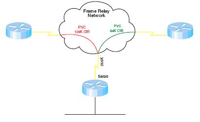
In this example, R1 has a 256 kbps connection to the Frame Relay network and two permanent virtual circuits (PVCs) with committed information rates (CIR) of 128 Kpbs and 64 Kbps. EIGRP divides the interface bandwidth evenly between the number of neighbors on that interface. What value should be used for the interface bandwidth in this case? The usual suggestion is to use the CIR, but the two PVCs have different CIRs. You could use the bandwidth-percent command to allow SNMP reporting of the true bandwidth value, while adjusting the interface burst rate to 25 percent, or 64 kbps.

R1(config)#int serial 0/0/0

R1 (config-if)#bandwidth 256

R1 (config-if)#ip bandwidth-percent eigrp 7 25

A better solution is to use sub-interfaces and identify bandwidth separately.

In the following example, s0/0/0.1 bursts to 64 k, and s0/0/0.2 bursts to 32 k, using EIGRP’s default value of half the bandwidth.

R1(config)#int serial 0/0/0.1

R1 (config-if)#bandwidth 128

!

R1(config)#int serial 0/0/0.2

R1 (config-if)#bandwidth 64

In cases where the hub interface bandwidth is oversubscribed, it may be necessary to set bandwidth for each sub-interface arbitrarily low, and then specify an EIGRP bandwidth percent value over 100 in order to allow EIGRP to use half the PVC bandwidth.